
Product 03 · Post-processing
Mandrel extractor
Equipment for controlled mandrel removal after composite part curing, engineered around geometry, travel, extraction force and production flow.
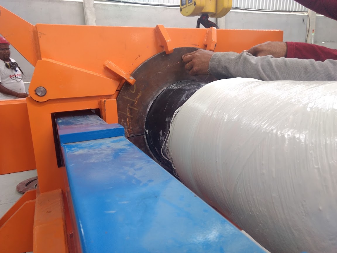
Technical specifications
Extraction sized for the part and tooling.
The configuration accounts for actual demolding conditions, part support and mandrel movement. Final values are defined after the technical assessment.
| Application | Mandrel removal from components manufactured in composite materials. |
|---|---|
| Main process | Controlled demolding and mandrel extraction. |
| Available lines | Poles: 450 mm and 960 mm. Tubes: 1000 mm and 1200 mm. |
| Part and tooling | Diameter, length, weight and interfaces defined for the application. |
| Force and travel | Sized from extraction conditions and assembly geometry. |
| Clamping and support | Devices configured to stabilize the part and mandrel during operation. |
| Drive system | Technology, power and speed defined for the required force, travel and cycle rate. |
| Control | Local control or cell integration defined for the production sequence. |
| Safety | Guards and interlocks defined by the risk assessment and applicable standards. |
| Installation | Deployment defined according to layout, material handling and utilities. |
| Supply scope | Engineering, manufacturing and integration according to the proposal scope. |
Extraction force, travel, power, dimensions and cycle rate are specified after analysis of the part, mandrel and process.
Available configurations
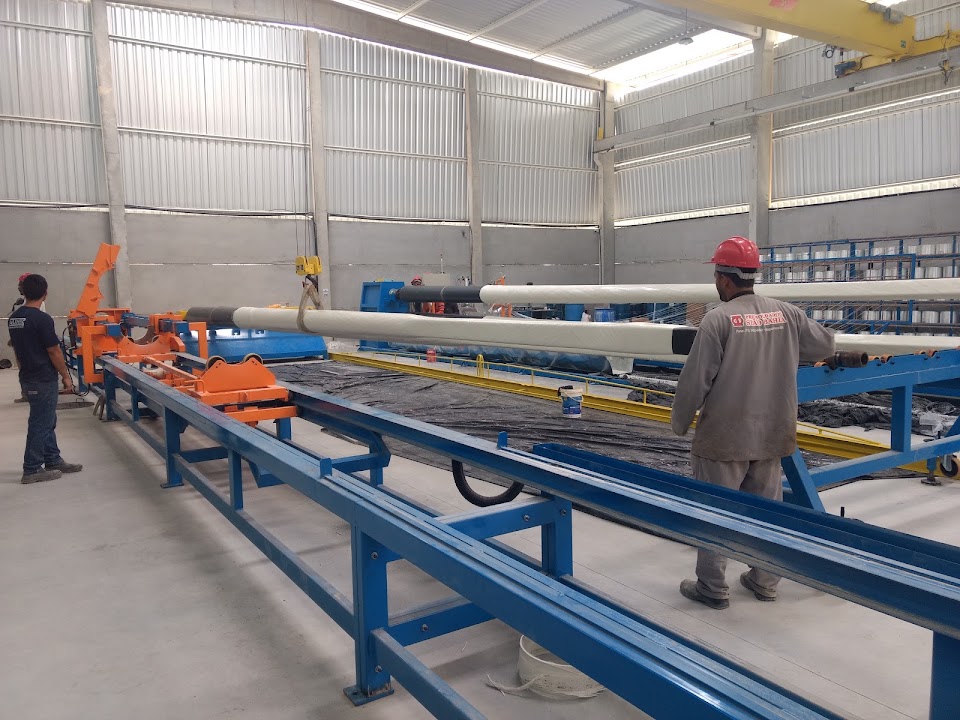
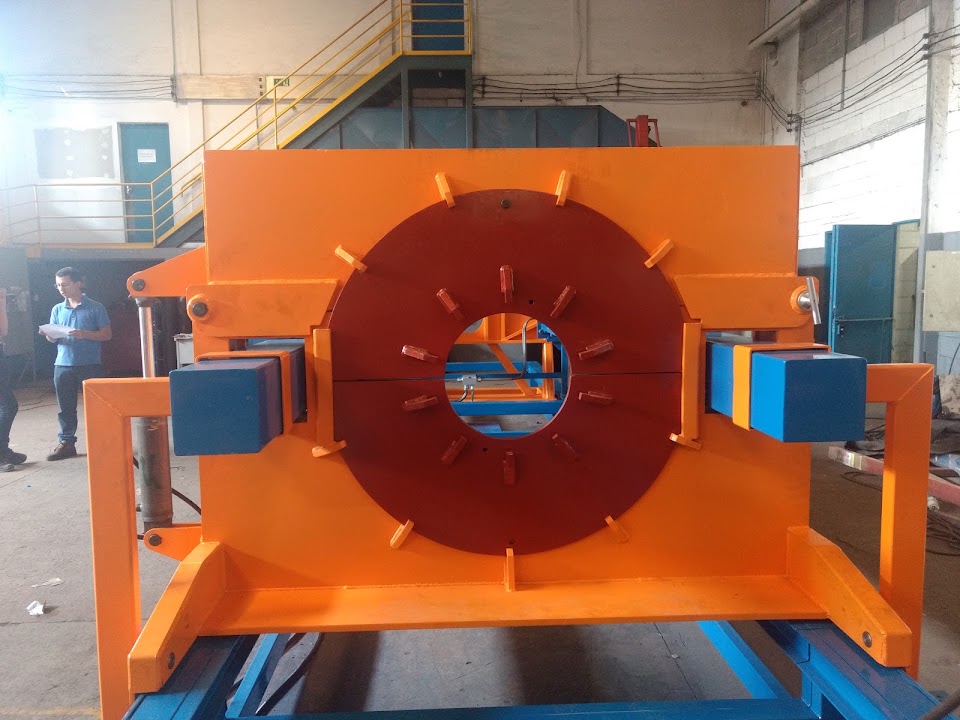
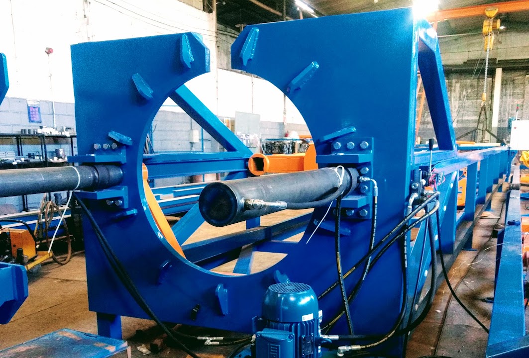
Four lines for poles and tubes.
Real equipment
Solutions built for different diameters.
AUMEK lines for controlled mandrel extraction in composite poles and tubes.
Integrated engineering
What the project takes into account.
Part and mandrel
Geometry, weight, interfaces, curing conditions and extraction force.
Operation
Supports, clamps, drive system, controls and safe demolding sequence.
Integration
Layout, handling, production-line interfaces and supply documentation.
Next equipmentPultrusion line
View specifications